
how does lens films work?

A lens film—usually called a coating or film layer—works by manipulating light at a microscopic level using thin-film physics. Each film is only nanometers to microns thick, yet it completely changes how the lens behaves. Here’s how:

1. What Is a Lens Film?

A lens film is a thin, transparent layer deposited on the lens surface. It’s not a sticker or paint—it’s bonded at the molecular level using vacuum deposition, chemical vapor deposition, or spin coating.Film Type Thickness PurposeHard coat 2–10 microns Scratch resistanceAR coating 100–500 nm Reduce reflectionHydrophobic 5–20 nm Repel waterOleophobic 5–20 nm Repel oilUV block 100–300 nm Block UVMirror 50–200 nm Reflect lightPhotochromic 10–50 microns Darken in UV

2. The Core Physics: Thin-Film InterferenceThis is the key principle behind most functional films:

Light hits film surface ↓Part reflects off TOP of film ↓Part travels through film ↓Part reflects off BOTTOM of film ↓Two reflected waves interfere“`· If waves are in phase → they add up (bright reflection)· If waves are out of phase → they cancel (no reflection)Film thickness controls which wavelengths cancel or amplify.

3. How Anti-Reflective (AR) Film WorksAR coating uses destructive interference to eliminate reflection:· Film thickness = ¼ wavelength of light· Light reflecting off top surface and bottom surface are 180° out of phase· They cancel each other out· Result: More light passes through, less glareSingle-layer AR:· Works for one wavelength (usually green, 550 nm)· Leaves purple/blue residual reflectionMulti-layer AR:· Stacks 4–9 layers of different materials· Each layer targets a different wavelength· Broad-spectrum reflection reduction· Result: Nearly invisible lens

4. How Hard Coat Film WorksHard coat is a polymer or silica-based layer that:· Increases surface hardness (3–5 H pencil hardness)· Resists scratches from cleaning, dropping, wearing· Acts as a base for other coatings· Applied by dip coating or spin coating· Cured with heat or UVWithout hard coat, AR coating would scratch off easily.

5. How Hydrophobic & Oleophobic Films WorkThese are surface energy modifiers:Hydrophobic (water-repelling)· Low surface energy → water beads up· Contact angle > 90°· Water rolls off, taking dust with it· Made from fluoropolymers or silanesOleophobic (oil-repelling)· Repels skin oils, fingerprints· Makes cleaning easier· Often combined with hydrophobic in one layerHow it works:

Water droplet on untreated lens → spreads flatWater droplet on treated lens → beads up and rolls off“`The film changes the surface energy so liquids can’t spread.

6. How UV-Blocking Film Works

Two mechanisms:Absorption· Organic UV absorbers in the film· Absorb UV photons, convert to heat· Example: benzotriazole compoundsReflection· Dielectric mirror layers· Reflect UV wavelengths back· Transparent to visible lightStack design:“`UV → [reflected] ← filmVisible → [passes through] → eye

7. How Mirror Film WorksMirror coating is a dielectric stack or metallic layer:· Metallic: Thin chromium or silver layer (5–50 nm)· Dielectric: Multiple layers of alternating high/low index materials· Reflects specific wavelengths· Can be tuned for color (blue, green, red mirror)How it reflects:· Each layer adds to reflected wave· Bragg reflection amplifies specific wavelengths· Result: Strong mirror effect at chosen color

8. How Photochromic Film WorksPhotochromic lenses contain silver halide crystals or organic molecules:“`UV hits film ↓Molecule changes shape (isomerization) ↓Absorbs visible light → darkens ↓UV removed ↓Molecule returns to original shape → clears“`· Inorganic (silver halide): Slower, lasts longer· Organic (spirooxazine): Faster, can be in-film or in-mass

9. How Films Are AppliedMethod How it works Used forVacuum deposition Vaporized material condenses on lens AR, mirror, hard coatSputtering Ions knock material onto lens AR, conductive filmsSpin coating Liquid spun evenly, then cured Hard coat, photochromic Dip coating Lens dipped in solution, withdrawn slowly Hard coat, hydrophobicCVD Gas reacts on surface to form film Specialty coatings

10. How Films Stack TogetherA modern premium lens has 7–12 layers:┌─────────────────────────────┐│ Hydrophobic (5 nm) │ ← Water repels├─────────────────────────────┤│ Oleophobic (5 nm) │ ← Oil repels├─────────────────────────────┤│ AR Layer 4 (100 nm) │ ← Blue block├─────────────────────────────┤│ AR Layer 3 (100 nm) │ ← Green cancel├─────────────────────────────┤│ AR Layer 2 (100 nm) │ ← Red cancel├─────────────────────────────┤│ AR Layer 1 (100 nm) │ ← Base AR├─────────────────────────────┤│ Hard Coat (5 microns) │ ← Scratch resist├─────────────────────────────┤│ UV Absorber (in material) │ ← UV block├─────────────────────────────┤│ Lens Material │ ← CR-39, poly, etc.└─────────────────────────────┘“`

Each layer has a specific job. Together, they create a complete optical defense system.

11. The Full Film Function Chain“`Light hits lens ↓Hydrophobic layer → water rolls off ↓Oleophobic layer → oil repels ↓AR layers → reflection cancelled ↓UV layer → UV absorbed/reflected ↓Hard coat → protects below ↓Lens material → refracts light ↓Eye receives clean, safe, focused light“`🔑 The Core IdeaA lens film works by engineering light at the nanoscale. Each film uses one or more of these principles:

1. Interference — cancel or amplify specific wavelengths

2. Absorption — soak up harmful light

3. Reflection — bounce light away

4. Surface energy — control how liquids behave5. Hardness — protect the lens surfaceThe film doesn’t just sit on the lens—it actively manipulates light using physics that operates at the wavelength scale. That’s why a lens with 10 layers of film can cost more than the lens material itself.

Explore to go deeper into any part—like how AR stacks are designed, how photochromic molecules work, or how films are tested for durability?
how light passes through lens?

Light passing through a lens is a story of refraction — the bending of light as it changes speed between materials. Here’s how it works:

1. The Fundamental Principle: RefractionLight travels at different speeds in different materials:· Air: ~300,000 km/s (fastest)· Glass/Plastic: ~200,000 km/s (slower)·

High-index material: ~170,000 km/s (even slower)When light hits a lens surface at an angle, the speed change causes it to bend. This is governed by Snell’s Law:“`n₁ × sin(θ₁) = n₂ × sin(θ₂)“`Where:· n = refractive index of each material· θ = angle of light relative to the surface normal

2. Why a Curved Surface Matters A flat glass sheet doesn’t focus light — it just shifts it slightly. A curved surface makes the bending uneven:· Center of lens: Light hits nearly perpendicular → bends slightly· Edge of lens: Light hits at a steep angle → bends moreThis difference in bending is what converges (convex lens) or diverges (concave lens) light.

3. Convex Lens (Converging)Used for hyperopia (farsightedness):“`Light rays → ) → converge to a point“`· Parallel rays enter the lens· Each ray bends toward the center axis· All rays meet at the focal point· The distance from lens to focal point = focal lengthThe thicker the center, the shorter the focal length, the stronger the lens.

4. Concave Lens (Diverging)Used for myopia (nearsightedness): Light rays → ( → spread apart Parallel rays enter the lens· Each ray bends away from the center axis· Rays appear to come from a virtual focal point behind the lens· The thicker the edge, the stronger the divergence

5. The Two-Surface JourneyLight actually bends twice — once entering, once exiting:Stage What happensEntering Light slows down, bends toward normalTraveling inside Light moves through lens materialExiting Light speeds up, bends away from normalThe combined effect of both surfaces determines the final direction. This is why lens designers can create complex prescriptions by varying both front and back curves independently.

6. How the Eye Receives ItThe lens’s job is to pre-focus light so the eye’s own lens can finish the job:· Perfect vision: Light converges exactly on the retina· Myopia: Light converges before the retina → concave lens diverges it back· Hyperopia: Light would converge behind the retina → convex lens converges it forward· Astigmatism: Light converges at multiple points → cylindrical lens corrects one axis

7. Beyond Simple RefractionModern lenses do more than just bend light:· Aspheric surfaces: Vary curvature across the lens to reduce aberrations· Diffractive zones: Tiny ridges that bend light through interference (used in multifocal IOLs)· Gradient index (GRIN): Material changes refractive index internally, bending light gradually· Coatings: Thin films that control reflection, transmission, and wavelength8. The Full Path — Step by Step“`

1. Light wave hits front surface

2. Refracts (bends) based on curvature + index

3. Travels through lens material

4. Hits back surface

5. Refracts again based on back curvature

6. Exits toward the eye

7. Cornea bends it further

8. Eye’s crystalline lens fine-tunes it

9. Lands on retina → signal to brain → vision🔑

The Core IdeaLight passing through a lens is controlled refraction. The curve of the surface, the material’s refractive index, and the angle of incoming light all work together to bend rays precisely where they need to go.

A lens doesn’t “focus” light by magic — it shapes the path of every ray so they all arrive at the same point.Want me to go deeper into any part — like how Snell’s Law is derived, how aspheric lenses reduce aberration, or how the eye’s lens works with the cornea?

How does software bringing vision into reality?

Software brings vision into reality by acting as the translator between abstract optical theory and physical machine movement.

It converts numbers (prescription, measurements) into geometry (a 3D surface), then into machine code (coordinates), and finally into a real lens.

Here’s the full chain:

1. From Prescription to Mathematical ModelThe software starts with raw data:· Sphere, cylinder, axis, add power, prism· PD, fitting height, frame trace· Pantoscopic tilt, wrap angle, vertex distanceIt then builds a virtual eye-lens system — a 3D mathematical model that simulates how light rays travel through the lens and where they land on the retina.

2. Ray Tracing — Simulating VisionThis is the heart of the process:· The software fires thousands of light rays through the virtual lens· Each ray is traced using Snell’s Law at every surface point· It calculates where each ray focuses — center, edge, corridor, periphery· It measures aberrations (blur, distortion, color fringing) at every pointThe goal: minimize error across the entire lens surface, not just the center.

3. Optimization — Finding the Best SurfaceThe software doesn’t just calculate one surface — it iterates:· FreeForm design: The surface is divided into a grid (e.g., 10,000+ points)· Each point’s curvature is adjusted slightly· Ray tracing runs again· An error function scores the result· The software repeats until the error is minimizedThis is called iterative optimization — the same principle used in aerospace and AI training.

4. Compensation — Matching Real LifeA lens on a computer isn’t a lens on a face. Software applies corrections:Factor What software doesPantoscopic tilt Tilts the optical axis in the modelWrap angle Rotates the surface mathematicallyVertex distance Adjusts effective powerFrame curve Warps the edge geometryReading inset Shifts near zone inwardWithout this, the patient gets blur or headaches — especially in high prescriptions.

5. From Surface to Machine CodeOnce the optimal surface is calculated:· The 3D surface is converted into a point cloud (X, Y, Z coordinates)· This becomes CNC toolpaths — instructions for the diamond lathe· The software adds tool compensation (accounting for tool radius, wear, vibration)· It also applies material shrinkage factors (plastics expand/contract during curing)

6. Simulation Before CuttingModern software runs a virtual manufacturing simulation:· Predicts surface quality· Checks for tool collisions· Verifies thickness at every point· Confirms the lens will fit the frameOnly after passing simulation does the file go to the machine.

7. Closing the Loop — Feedback & LearningAfter manufacturing:· The lens is measured (focimeter, lensmapper, wavefront sensor)· Results are fed back into the software· If errors exist, the design algorithm is adjusted· Over time, the software learns the behavior of each material and machineThis is called closed-loop manufacturing — the same concept behind self-driving cars and smart factories.8. The Full Digital Thread“`Prescription → Optical Model → Ray Tracing → Optimization → Compensation → Point Cloud → CNC Code → Machining → Inspection → Feedback → Improved Design“`Every step is software-driven. The factory isn’t just making a lens — it’s executing a mathematical vision that was calculated, tested, and verified entirely in the digital world before a single photon passes through the finished product.🔑 The Core IdeaSoftware brings vision into reality by:1. Modeling how light should behave2. Optimizing the surface to achieve it3. Compensating for real-world conditions4. Translating geometry into machine instructions5. Verifying and learning from every lens madeIt’s the bridge between optical science and physical manufacturing — and it’s why modern lenses can be personalized to a degree that was impossible even 20 years ago.

Learn more by dwelling into by any part — like how ray tracing algorithms work, how CNC code is generated, or how AI is now being used in lens design?

How does lens manufacturing factory process the information and make best lens design by mentioning all the process?

A lens manufacturing factory turns raw prescription data into a finished lens by routing it through an interconnected digital pipeline of design software, lab management systems (LMS), and CNC machines.

The “best” design is achieved by calculating the exact surface geometry for that specific order, rather than picking the closest match from a shelf.Here is how the factory processes the information and executes the design, step-by-step.📥

Step 1: Information Capture & TransmissionThe process begins at the optical store or clinic. The optician enters the patient’s prescription (power, astigmatism, prism), along with frame measurements and fitting data (like pupillary distance and fitting height). This order, often containing dozens of parameters, is transmitted to the factory’s server via a secure connection.🖥️

Step 2: The Lab Management System (LMS)The factory’s LMS (e.g., Rx-Universe, Innovations) acts as the central brain. It receives the order and performs crucial logistical and computational tasks:· Blank Selection: It automatically selects the correct semi-finished lens blank (material, base curve, size) from the inventory database based on the order and available stock.· Data Routing: It routes the order data to the design software (LDS) and prepares the work ticket for the production floor.📐

Step 3: Digital Lens Design (The Core Calculation)This is where the unique design is created. The factory’s design computer uses sophisticated software (like Zemax or CODE V) to calculate the exact 3D surface needed.· Applying Wearing Conditions: Unlike a generic stock lens, the software inputs real-world data. It calculates the necessary inset (the inward shift of the reading zone) based on the inter-pupillary distance and vertex distance. It also compensates for pantoscopic tilt and the frame’s wrap angle to ensure the optical center is perfectly aligned with the eye.· Aberration Control: The software generates a point cloud or mathematical surface that minimizes optical distortions (aberrations) across the entire lens, not just the center.⚙️

Step 4: Translating Design to Manufacturing DataThe abstract 3D design is converted into machine instructions.· CNC Code Generation: The design software outputs a “point file” or CNC code—a series of precise X, Y, Z coordinates that the machines will follow.· Compensation Factors: The system automatically applies “reverse shrinkage” or expansion factors. This anticipates how much the material will change during casting or coating, ensuring the final product matches the calculated design.🏭 Step 5: Physical Manufacturing (Freeform Surfacing)The factory now executes the digital plan on the lens blank.· Blocking: The chosen blank is “blocked” (held securely) so the machine knows its exact orientation.· Freeform Generation: A multi-axis CNC freeform generator uses diamond cutting tools to carve the complex surface calculated in

Step 5. It performs rough, smooth, and finish cuts, removing material down to micron precision. This is how complex progressive surfaces are created directly on the lens, rather than being molded into a generic shape.🔍

Step 6: Verification & FinishingBefore leaving the factory, the lens is checked and finished.· Inspection: The lens undergoes optical and surface inspection (using tools like a focimeter or 3D profilometer) to verify the power, axis, and surface quality match the digital design.· Coating & Edging: The lens is coated (AR, hard coat, etc.) and then edged to fit the specific frame shape that was ordered.🔑 The Key to a “Best” DesignThe system makes the “best” lens because it no longer relies on a finite number of pre-made progressive blanks. Instead, it calculates a unique, optimized surface for every single order, integrating the patient’s prescription with how the glasses will actually sit on their face.

How does lens engineering works?

Lens engineering is the science of designing and manufacturing a lens so that light lands exactly where it should on the retina — for every gaze direction, every prescription, and every frame. Here’s how it works:

1. Optical Design FundamentalsEvery lens is defined by a few core parameters:· Front base curve — the starting curvature of the lens blank· Back surface curve — where the prescription is cut· Center thickness — minimum material needed for safety and optics· Edge thickness — determined by power and frame shapeThe engineer calculates how these curves bend light using Snell’s Law and lensmaker’s equations, then optimizes for the patient’s specific prescription.

2. Aberration ControlReal lenses aren’t perfect — engineers must correct for:Aberration What it does How it’s correctedSpherical Blurs off-axis vision Aspheric curvesComa Comet-shaped blur Athermal/aspheric designAstigmatism (oblique) Skewed focus off-axis Tilted/compensated curvesChromatic Color fringing High-index + Abbe value matchingDistortion Straight lines look curved Pantoscopic tilt compensationAspheric lenses are a key tool — they vary curvature across the surface to flatten the lens and reduce aberrations, especially for high prescriptions.

3. FreeForm / Digital SurfacingThis is the biggest revolution in lens engineering:· Traditional lenses use spherical front and back curves — limited to stock designs· FreeForm uses a point-by-point mathematical surface that changes curvature continuously· The design software simulates thousands of ray paths to optimize the surface· A diamond-cutting lathe then carves that exact surfaceThis allows:· Personalized progressives matched to how the wearer actually moves their eyes· Atoric corrections for astigmatism· Compensation for frame tilt, wrap angle, and vertex distance

4. Compensation FactorsA lens doesn’t sit in a vacuum — engineers account for real-world wearing conditions:· Pantoscopic tilt — frame tilt downward (~8–12°)· Face form / wrap — how much the frame curves around the face· Vertex distance — gap between lens and eye· Optical center placement — aligned to pupil, not frame centerIf these aren’t compensated, the patient gets blur, distortion, or headaches — especially in high prescriptions.

5. Material Engineering The lens material affects weight, thickness, and optics:Material Index Abbe Best forCR-39 1.50 58 Low Rx, best opticsPolycarbonate 1.59 30 Safety, kidsTrivex 1.53 45 BalanceHigh-index 1.67 1.67 32 Thin, moderate-high RxHigh-index 1.74 1.74 33 Thinnest possibleEngineers balance index of refraction (thinner lenses) vs. Abbe value (less chromatic aberration). Higher index = thinner but more color fringing.

6. Progressive Lens DesignThe hardest engineering challenge:· Distance zone (top) — clear far vision· Intermediate corridor — gradual power change· Near zone (bottom) — reading· Peripheral zones — unavoidable blur that must be minimizedEngineers use soft vs. hard designs:· Soft: wider corridor, more peripheral blur· Hard: narrower corridor, clearer peripheryModern designs use variable inset, corridor length optimization, and binocular balance so both eyes work together.

7. Manufacturing PrecisionThe engineering translates to production via:· CNC generators — cut the back curve to micron accuracy· Polishing robots — maintain surface quality· Coating chambers — deposit nanometers-thick layers· Edgers — cut to frame shape (as discussed earlier)Each step has tolerances — typically ±0.06 diopters for power and ±2° for axis.8. Verification & FeedbackAfter manufacturing:· Focimeter checks power, axis, prism· Lensmapper verifies progressive corridor placement· Wavefront sensors (high-end) measure actual optical performanceIf a lens fails, the design parameters are adjusted and re-run.🔑 The Core IdeaLens engineering = ray tracing + aberration correction + real-world compensation + precision manufacturing. The goal is a lens that doesn’t just match a prescription on paper, but delivers clear, comfortable vision for how the wearer actually uses their eyes.

Search for more and go more deeper into any area — like progressive design software, aspheric math, or how FreeForm lathes achieve micron accuracy?

How does lens get made?

Lens manufacturing is a multi-stage process that turns a raw material into a precision optical device. Here’s the full journey:

1. Material CreationPlastic (most common):· Liquid monomer (like CR-39, polycarbonate, or high-index) is poured into a glass mold· Cured using heat or UV light until it hardens into a lens blank· The blank is a semi-finished disc — one side curved, the other flat or roughly shapedGlass:· Molten glass is poured into molds or pressed into lens blanks· Requires slower, hotter curing cycles

2. Surfacing (Creating the Prescription)This is where the optical power is ground into the lens:· Generator: A diamond-cutting tool carves the back surface to the required curve (base curve + prescription)· Fining: Finer abrasives smooth out the rough-cut surface· Polishing: The lens is polished to optical clarity using slurry and pads· Result: A lens with the correct front and back curves but still oversized and uncutFor progressive lenses, the back surface is free-form generated with complex, continuously changing curves — often using digital surfacing (FreeForm) technology for pinpoint accuracy.

3. CoatingBefore edging, lenses go through coating stages:Coating PurposeHard coat Scratch resistanceAR (Anti-Reflective) Reduces glare, improves clarityHydrophobic Repels waterOleophobic Repels oil/smudgesUV/Blue light Blocks harmful lightCoatings are applied in vacuum chambers using vapor deposition — layers only nanometers thick.4. Edging (Fitting to the Frame)This is where the edger comes in (as we discussed):· The lens is centered to the patient’s pupil position· Tracing: The frame shape is digitized· Edging: The machine grinds the lens perimeter to match the frame· Beveling: A V-shaped groove is cut into the edge so it sits in the frame· Safety bevel: A small chamfer on the front edge5. Final Assembly & Inspection· Lens is inserted into the frame· Verification: Focimeter checks the power matches the prescription· Tinting (optional): Lenses can be dyed for sunglasses· Final QC for scratches, coating defects, and axis alignment🔑 Key Precision Points· FreeForm digital surfacing allows each lens to be made to exact prescription + frame curve· Axis alignment must be accurate to within 1–2 degrees for astigmatism· Center thickness is controlled to meet impact safety standards (especially polycarbonate)The whole process typically takes 1–3 days in a lab, though in-office edging can complete it in under an hour.

More deeper dive like search for

Learn more about — like FreeForm technology, coating science, or how progressive lenses are designed?

How does lens gets precise shape when it get into lens edger machine?

A lens edger achieves precision through a combination of mechanical stability and computer-controlled measurement that accounts for how the lens behaves while clamped.🛠️ Mechanical Precision: Clamping & StabilityBefore grinding begins, the machine must hold the lens securely without distortion. Specialized clamping systems use rubber or water bags to apply even pressure, preventing the lens from slipping or deviating from its intended axis. Once locked in place, the edger uses a digital template or “trace data” of the frame shape to guide the grinding wheel.📏 Measurement Precision: The “Feeling” ProcessThe real precision comes from a process called “feeling” (tracing), which happens after the lens is clamped. When a lens is squeezed between the shafts, it can deform slightly. The machine compensates for this:· Reference Points: The machine probes a small sample of points (e.g., 10 points) on the lens surface while it’s clamped, comparing them to a larger pre-measured dataset (e.g., 360 points) taken before clamping.· Deformation Modeling: By measuring this small sample, the computer deduces exactly how much the lens has flexed or shifted. It then adjusts the grinding path to ensure the final shape is correct despite the clamping pressure.🖥️ Digital Control & CalibrationModern edgers rely on microprocessors that continuously translate the lens across the wheel while monitoring the grinding force and speed. They also feature automatic calibration (like MEI’s DCU EVO), which measures the exact diameter of the cutting tools and the lens axis position without interrupting production, ensuring the machine doesn’t drift out of alignment over time.If you’re interested in a specific type of lens (like progressive or high-wrap sunglasses), the precision methods can vary slightly.

How rimless frames are engineered?

Rimless frames are engineered through precision mounting systems that attach the bridge and temples directly to the lenses—no surrounding frame material. The engineering challenge is balancing invisibility with structural security.🔩

Core Mounting MethodsScrew-Mounted (Traditional Drill Mount)The most common approach. Two or more through-bores are drilled into the lens edge area. The bridge and end pieces have barbed metal pins or threaded posts that pass through these holes, secured with screws and nuts or compression bushings .

A patent describes using a plastic filament (nylon) through auxiliary holes to invisibly anchor the bridge and temple elements, keeping hardware hidden .Compression/Clamp MountingA newer approach that avoids drilling entirely. The bridge and end pieces have protrusions that clamp onto the lens surface. The fixing body is lowered over the lens and fastened with a nut, creating a pressure seal . This prevents lens cracking from shock and extends lens life by eliminating holes as stress points.

Groove-Mounted (Rimway/Cortland Style)A groove is cut around the lens edge. A support line (often fishing line or nylon) sits in the groove and threads through holes in the bridge and end pieces . This provides stability while keeping the attachment nearly invisible.📐 Engineering the Drill HolesDrilling rimless lenses requires precision to avoid star cracks or flaking:· Hole angle: The system must account for the surface curve of the demo lens versus the actual prescribed lens. A software method selects drilling angles—normal to the demo lens, normal to the actual lens, or arbitrarily set—and calculates hole position data to compensate for curvature differences .·

Material selection: Trivex is preferred for drilled rimless because it is least affected by drilling, reducing star cracks. Its tensile strength allows thinner edges without chipping . Polycarbonate is also recommended for safety .· Edge thickness: A minimum of 2.0 to 2.2 mm edge thickness is maintained for groove-mount rimless. High-index lenses with thinner edges (1.8 mm) flake during fabrication or later .🔧 Structural Stability SystemsTo prevent lenses from rotating or shifting, engineers add:· Anti-rotation features: Non-cylindrical pins (oval, square) prevent relative rotation between lens and mount .· Three-point fit: Nose pads and temples create tripod stability, keeping lenses aligned .· Spring hinges: Integrated spring mechanisms allow temples to flex without breaking the mount .⚠️

Trade-OffsRimless frames are lightest and most invisible but least durable. The mounting points are stress concentrators—loose screws cause lens shift, affecting vision and risking cracks . They require more frequent professional checks of mounting hardware .Would you like to explore specific mounting hardware designs, or how drilling parameters are calculated for different lens curvatures?

how does spectacles made?

Making spectacles is a blend of precision optics, digital design, and manual craftsmanship. The process moves from a raw material to a finished pair in roughly 10–15 steps. Here is how it works:📋

1. The Prescription & Order· An optometrist writes your prescription (sphere, cylinder, axis, PD, add).· You choose a frame and lens type (single vision, progressive, photochromic, coatings).· The order goes to a lens lab or factory.🔬

2. Lens Design (Digital)· The prescription is entered into computer-aided design (CAD) software.· For free-form lenses, AI calculates the exact surface geometry needed for your eye.· The software outputs a file that tells the machine how to cut the lens.🧱

3. Lens Blank Selection· A semi-finished blank (one side pre-curved, one side flat) is selected.· Material: CR-39, polycarbonate, Trivex, or high-index plastic.· The blank is chosen based on your prescription strength and lens index.⚙️

4. Surfacing (Cutting the Prescription)· The blank is mounted on a blocker (holds it in place).· A generator (diamond-cutting lathe) carves the back surface to match your prescription.· Free-form generators cut complex, custom curves for progressive lenses.· The lens is now optically correct but still rough.🔄

5. Fine Grinding & Polishing· The lens goes through fine grinding to smooth the surface.· Then polishing with a slurry to make it optically clear.· Any remaining surface imperfections are removed.🧪

6. Hard Coating· A scratch-resistant coating is applied (often via spin coating or dip coating).· The lens is cured under UV light or heat.🎨

7. Tinting & Coatings (Optional)· Tinting: Lens is dipped in dye for sunglasses or fashion tints.· Anti-reflective (AR): Multiple thin layers are deposited in a vacuum chamber.· Mirror coating: Metallic layers applied for reflective look.· Hydrophobic/oleophobic: Repels water and oil.· Blue light filter: Blocks specific wavelengths.✂️

8. Edging (Cutting to Frame Shape)· The lens is cut to the exact shape of your frame.· A pattern or digital tracer provides the frame shape.· The edger grinds the lens edge to fit the frame groove.🔧

9. Frame Assembly· The lenses are inserted into the frame.· For rimless frames, holes are drilled and screws/mounts installed.· For metal frames, the lenses are snapped into the rim.📐

10. Final Alignment & Adjustment· The optician checks optical center alignment with your pupils.· Nose pads, temples, and tilt are adjusted for fit.· The frame is cleaned and inspected for defects.🧠

11. Quality Control· Lenses are checked for power accuracy, coating defects, and scratches.· A lensometer verifies the prescription.· Frame alignment is checked with a gauge.📦

12. Dispensing· The finished spectacles are given to you with fitting instructions.· Follow-up adjustments are made if needed.🏭 Factory vs. In-Store LabFeature Factory Lab In-Store LabVolume High LowCustomization Free-form, complex StandardTurnaround 3–7 days Same dayCost Lower per unit Higher per unitCoatings Full range Limited💡 Key InsightSpectacles are made through a digital-to-physical pipeline:Prescription → CAD design → Surfacing → Polishing → Coating → Edging → Assembly → AlignmentThe most critical steps are surfacing (cutting the correct curve) and alignment (centering the lens on your pupil). Everything else—coatings, tinting, edging—adds comfort, durability, and style.Would you like to know how progressive lenses are specifically manufactured, or how frame materials are chosen?

what is the reflection technology? How does it work?

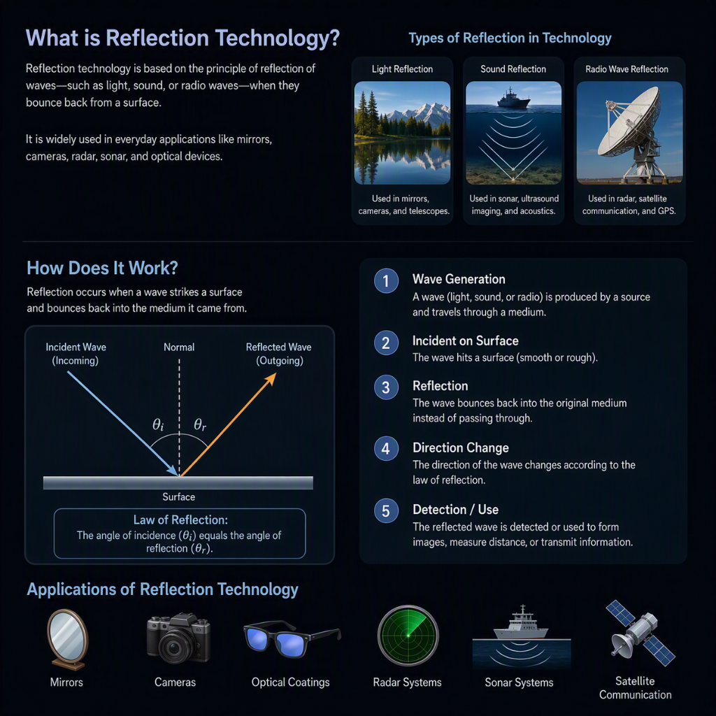
Reflection technology refers to systems that use the bouncing of light (or other waves) off surfaces to detect, measure, identify, or manipulate objects. It works on a simple principle: send a signal out, measure what comes back, and calculate what that tells you about the target.🔦 The Core PrincipleWhen light hits a surface, some of it reflects. How it reflects depends on:· Surface angle — flat mirrors reflect cleanly; rough surfaces scatter· Material — metal reflects differently than glass or skin· Wavelength — infrared, visible, and UV behave differently· Distance — time delay reveals how far away the object is📡 How It Works: Step by Step“`1. Emit a signal (light, laser, IR, radar, sound) ↓2. Signal travels to target ↓3. Signal bounces off target ↓4. Sensor captures the returning signal ↓5. System measures: time, angle, intensity, wavelength shift ↓6. Algorithm converts data into information“`🔬 Types of Reflection Technology1. Time-of-Flight (ToF)· Sends a pulse of light (usually IR)· Measures how long it takes to return· Formula: Distance = (Speed of Light × Time) ÷ 2· Used in: Depth cameras, LiDAR, iPhone Face ID2. LiDAR (Light Detection and Ranging)· Fires thousands of laser pulses per second in a grid pattern· Builds a 3D point cloud of the environment· Used in: Autonomous cars, drones, mapping, archaeology3. Radar (Radio Detection and Ranging)· Uses radio waves instead of light· Works through fog, rain, and darkness· Used in: Air traffic control, weather tracking, adaptive cruise control4. Sonar (Sound Navigation and Ranging)· Uses sound waves (underwater)· Measures echo return time· Used in: Submarine navigation, fishing, medical ultrasound5. Optical Reflectometry· Sends light into a fiber or surface· Analyzes the reflected pattern to detect faults, temperature, or strain· Used in: Fiber optic networks, structural health monitoring6. Specular vs. Diffuse Reflection Sensing· Specular: Mirror-like reflection — used in laser barcode scanners· Diffuse: Scattered reflection — used in optical mice, proximity sensors🧠 How the System Interprets ReflectionThe reflected signal carries information:What Changes What It RevealsTime delay Distance to objectAngle of return Direction and shapeIntensity Surface reflectivity, materialWavelength shift Speed of object (Doppler)Polarization change Surface roughness, stressPhase shift Sub-millimeter precision🏭 Real-World ApplicationsMedical Imaging· Optical Coherence Tomography (OCT): Uses reflected near-infrared light to create cross-sectional images of the retina — detecting macular degeneration, glaucoma, and even coronary plaque.Automotive· LiDAR and radar let self-driving cars “see” obstacles, lane markings, and pedestrians in 3D.Consumer Tech· Face ID: Projects 30,000 IR dots onto your face and measures the reflected pattern.· Optical mice: LED light reflects off the desk surface; a sensor tracks movement.· Proximity sensors: Your phone screen turns off when it detects your face’s reflection.Industrial· Laser profilometers: Scan surfaces to detect defects in manufacturing.· Fiber Bragg Grating sensors: Measure strain in bridges and pipelines via reflected wavelength shifts.Military & Aerospace· Laser range finders: Measure distance to targets.· Synthetic Aperture Radar (SAR): Creates high-resolution images through clouds and darkness.💡 Key InsightReflection technology works because light (or waves) carry information when they bounce. The system doesn’t just see the object—it measures how the object changed the signal. That change reveals distance, shape, material, motion, and even internal structure.Would you like to go deeper into a specific type, such as LiDAR for autonomous vehicles or OCT for medical imaging?