
how does lens works in non environment?

A lens in a harsh environment must survive conditions that would destroy an ordinary lens—extreme temperatures, impacts, chemicals, abrasives, and radiation. Here’s how lenses are engineered to work when everything is against them:

1. What Makes an Environment “Harsh”? Factor Examples Threat to LensImpact Dropping, debris, collisions Cracking, shatteringTemperature -40°C to +80°C Expansion, coating crackChemicals Solvents, acids, fuels Etching, cloudingAbrasives Sand, dust, grit Scratching, hazingRadiation UV, IR, lasers, nuclear Degradation, discolorationMoisture Rain, saltwater, humidity Fogging, delaminationPressure Deep sea, high altitude Stress fractureBiological Bacteria, fungi, sweat Biofilm, degradation

2. Material Selection — The First DefenseDifferent environments demand different lens materials:Material Best For WhyPolycarbonate Impact, safety 250× stronger than glassTrivex Impact + optics Better clarity than polyChemically strengthened glass High heat, chemicals Withstands extreme tempsSapphire Scratch, abrasion 9 Mohs hardness (near diamond)Quartz/Fused silica UV, high temp Transmits deep UV, heat resistantAcrylic (PMMA) General outdoor UV stable, lightweightKey principle: Match the material to the dominant threat.

3. Impact Protection — Surviving the HitPolycarbonate — The Gold Standard· Molecular structure: Carbonate groups absorb impact energy· Failure mode: Bends and deforms instead of shattering· Test: ANSI Z87.1 — 1/4″ steel ball at 150 ft/s· Limitation: Softer surface, scratches easily → needs hard coatTrivex· Better optical clarity than polycarbonate· Similar impact resistance· Lighter weight· Used in military, safety, and premium sports lensesLaminated Glass· Multiple glass layers + interlayer (PVB)· Used in: armored vehicles, bank teller windows, fighter jets· Cracks but doesn’t shatter — holds together

4. Temperature Extremes — Expanding and ContractingThe Problem· Materials expand when hot, contract when cold· Coating expands differently than lens → cracks, delamination· Adhesives fail at extremesThe SolutionApproach How it worksLow CTE materials Quartz, sapphire expand very littleMatched coatings Coating CTE matched to lens CTEFlexible adhesives Silicone-based, tolerate movementThermal cycling tests -40°C to +80°C cycles before shippingReal example: Aerospace lenses undergo 100+ thermal cycles before certification.

5. Chemical Resistance — Surviving the AttackThe Threat· Solvents dissolve coatings· Acids etch glass· Fuels, oils, hydraulic fluids penetrate· Saltwater corrodesThe SolutionCoating Protects AgainstSiloxane hard coat Mild chemicals, solventsFluoropolymer Acids, bases, fuelsParylene Everything — conformal barrierSapphire Nearly all chemicals except HFParylene is applied by vapor deposition—it forms a pinhole-free barrier only microns thick, protecting against acids, bases, and solvents.

6. Abrasion Resistance — Fighting Sand and GritThe Threat· Sand (7 Mohs) scratches glass (5.5 Mohs)· Dust wears down coatings· Repeated wiping creates micro-scratchesThe SolutionApproach Hardness NotesHard coat (siloxane) 3–5 H pencil Standard protectionDiamond-like carbon (DLC) 8–9 Mohs Near-sapphire hardnessSapphire 9 Mohs Best scratch resistanceAnti-abrasion AR Varies Scratch-resistant + anti-reflectiveDLC coating is used in:· Military goggles· Aerospace windows· High-end safety glasses· Infrared optics

7. UV & Radiation — Surviving the InvisibleThe Threat· UV degrades polymers → yellowing, brittleness· IR causes heat buildup → cracking· Nuclear radiation darkens glass· Lasers destroy coatingsThe SolutionRadiation ProtectionUV Cerium oxide in glass, UV absorbers in polymerIR Gold or dielectric mirror coatingsNuclear Cerium-doped quartz (radiation-hard)Laser Multi-layer dielectric mirrors, absorptive filtersCerium-doped quartz is used in nuclear reactors and space—it resists darkening from gamma radiation.

8. Moisture & Fogging — Seeing Through WaterThe Threat· Rain, sweat, humidity → fogging· Saltwater → corrosion· Condensation → vision blockedThe SolutionCoating How it worksHydrophobic Water beads and rolls offHydrophilic Water spreads into thin, clear film (anti-fog)Anti-fog Surfactant layer prevents droplet formationSealed edges Prevent moisture ingressDual-action coatings combine hydrophobic (outer) and hydrophilic (inner) for the best of both.

9. Pressure Extremes — Deep Sea to SpaceDeep Sea· Pressure up to 1,100 atm (Mariana Trench)· Lenses must be thick, spherical, or dome-shaped· Material: acrylic or sapphire· Housed in titanium or ceramic framesHigh Altitude / Space· Pressure differential → stress on seals· Temperature swings → thermal shock· Vacuum → outgassing of materials· Solution: quartz windows, indium seals, titanium housings

10. Biological Threats — Bacteria, Fungi, SweatThe Threat· Bacteria colonize lens surfaces· Fungi etch coatings· Sweat corrodes metal frames

The SolutionApproach How it works Antimicrobial coating Silver ions kill bacteriaEasy-clean surface Prevents biofilm adhesionSealed design No gaps for microbesAutoclavable materials Survive sterilizationUsed in: surgical loupes, medical endoscopes, military goggles.

11. The Full Harsh Environment Stack“`┌─────────────────────────────┐│ Anti-fog (hydrophilic) │ ← Prevents fogging├─────────────────────────────┤│ Hydrophobic (outer) │ ← Repels water├─────────────────────────────┤│ DLC / Sapphire │ ← Scratch resistance├─────────────────────────────┤│ AR Coating (multi-layer) │ ← Reduces glare├─────────────────────────────┤│ UV/IR Blocking Layer │ ← Blocks radiation├─────────────────────────────┤│ Parylene Barrier │ ← Chemical protection├─────────────────────────────┤│ Hard Coat │ ← Base protection├─────────────────────────────┤│ Polycarbonate / Sapphire │ ← Impact + material├─────────────────────────────┤│ Lens Material │ ← Core optics└─────────────────────────────┘“`12. Real-World ExamplesEnvironment Lens SolutionDesert Sapphire + DLC + hydrophobicArctic Anti-fog + hydrophobic + polycarbonateUnderwater Dome port + quartz + sealed housingSpace Quartz + indium seal + radiation-hardFactory Polycarbonate + hard coat + anti-fogMilitary Ballistic poly + DLC + AR + anti-fogChemical lab Parylene + sapphire + sealedNuclear Cerium-doped quartz + leaded glass13. Testing — Proving It WorksTest What it simulatesDrop test ImpactThermal cycling Temperature extremesSalt spray CorrosionAbrasion wheel Sand/dustUV exposure SunlightChemical soak Solvents/acidsPressure chamber Deep sea/altitudeBallistic test Bullets/fragments🔑

The Core IdeaA lens works in harsh environments by layering defenses:

1. Material — impact, temperature, chemical resistance

2. Coatings — scratch, UV, moisture, chemical protection

3. Design — sealed, reinforced, pressure-resistant4. Testing — proven against real-world threatsNo single material or coating does everything.

The art is in stacking the right combination for the specific environment—desert, deep sea, space, or battlefield.

Explore deeper into any part—like sapphire lens manufacturing, DLC coating process, or how military ballistic lenses are tested?
how does lens films work?

A lens film—usually called a coating or film layer—works by manipulating light at a microscopic level using thin-film physics. Each film is only nanometers to microns thick, yet it completely changes how the lens behaves. Here’s how:

1. What Is a Lens Film?

A lens film is a thin, transparent layer deposited on the lens surface. It’s not a sticker or paint—it’s bonded at the molecular level using vacuum deposition, chemical vapor deposition, or spin coating.Film Type Thickness PurposeHard coat 2–10 microns Scratch resistanceAR coating 100–500 nm Reduce reflectionHydrophobic 5–20 nm Repel waterOleophobic 5–20 nm Repel oilUV block 100–300 nm Block UVMirror 50–200 nm Reflect lightPhotochromic 10–50 microns Darken in UV

2. The Core Physics: Thin-Film InterferenceThis is the key principle behind most functional films:

Light hits film surface ↓Part reflects off TOP of film ↓Part travels through film ↓Part reflects off BOTTOM of film ↓Two reflected waves interfere“`· If waves are in phase → they add up (bright reflection)· If waves are out of phase → they cancel (no reflection)Film thickness controls which wavelengths cancel or amplify.

3. How Anti-Reflective (AR) Film WorksAR coating uses destructive interference to eliminate reflection:· Film thickness = ¼ wavelength of light· Light reflecting off top surface and bottom surface are 180° out of phase· They cancel each other out· Result: More light passes through, less glareSingle-layer AR:· Works for one wavelength (usually green, 550 nm)· Leaves purple/blue residual reflectionMulti-layer AR:· Stacks 4–9 layers of different materials· Each layer targets a different wavelength· Broad-spectrum reflection reduction· Result: Nearly invisible lens

4. How Hard Coat Film WorksHard coat is a polymer or silica-based layer that:· Increases surface hardness (3–5 H pencil hardness)· Resists scratches from cleaning, dropping, wearing· Acts as a base for other coatings· Applied by dip coating or spin coating· Cured with heat or UVWithout hard coat, AR coating would scratch off easily.

5. How Hydrophobic & Oleophobic Films WorkThese are surface energy modifiers:Hydrophobic (water-repelling)· Low surface energy → water beads up· Contact angle > 90°· Water rolls off, taking dust with it· Made from fluoropolymers or silanesOleophobic (oil-repelling)· Repels skin oils, fingerprints· Makes cleaning easier· Often combined with hydrophobic in one layerHow it works:

Water droplet on untreated lens → spreads flatWater droplet on treated lens → beads up and rolls off“`The film changes the surface energy so liquids can’t spread.

6. How UV-Blocking Film Works

Two mechanisms:Absorption· Organic UV absorbers in the film· Absorb UV photons, convert to heat· Example: benzotriazole compoundsReflection· Dielectric mirror layers· Reflect UV wavelengths back· Transparent to visible lightStack design:“`UV → [reflected] ← filmVisible → [passes through] → eye

7. How Mirror Film WorksMirror coating is a dielectric stack or metallic layer:· Metallic: Thin chromium or silver layer (5–50 nm)· Dielectric: Multiple layers of alternating high/low index materials· Reflects specific wavelengths· Can be tuned for color (blue, green, red mirror)How it reflects:· Each layer adds to reflected wave· Bragg reflection amplifies specific wavelengths· Result: Strong mirror effect at chosen color

8. How Photochromic Film WorksPhotochromic lenses contain silver halide crystals or organic molecules:“`UV hits film ↓Molecule changes shape (isomerization) ↓Absorbs visible light → darkens ↓UV removed ↓Molecule returns to original shape → clears“`· Inorganic (silver halide): Slower, lasts longer· Organic (spirooxazine): Faster, can be in-film or in-mass

9. How Films Are AppliedMethod How it works Used forVacuum deposition Vaporized material condenses on lens AR, mirror, hard coatSputtering Ions knock material onto lens AR, conductive filmsSpin coating Liquid spun evenly, then cured Hard coat, photochromic Dip coating Lens dipped in solution, withdrawn slowly Hard coat, hydrophobicCVD Gas reacts on surface to form film Specialty coatings

10. How Films Stack TogetherA modern premium lens has 7–12 layers:┌─────────────────────────────┐│ Hydrophobic (5 nm) │ ← Water repels├─────────────────────────────┤│ Oleophobic (5 nm) │ ← Oil repels├─────────────────────────────┤│ AR Layer 4 (100 nm) │ ← Blue block├─────────────────────────────┤│ AR Layer 3 (100 nm) │ ← Green cancel├─────────────────────────────┤│ AR Layer 2 (100 nm) │ ← Red cancel├─────────────────────────────┤│ AR Layer 1 (100 nm) │ ← Base AR├─────────────────────────────┤│ Hard Coat (5 microns) │ ← Scratch resist├─────────────────────────────┤│ UV Absorber (in material) │ ← UV block├─────────────────────────────┤│ Lens Material │ ← CR-39, poly, etc.└─────────────────────────────┘“`

Each layer has a specific job. Together, they create a complete optical defense system.

11. The Full Film Function Chain“`Light hits lens ↓Hydrophobic layer → water rolls off ↓Oleophobic layer → oil repels ↓AR layers → reflection cancelled ↓UV layer → UV absorbed/reflected ↓Hard coat → protects below ↓Lens material → refracts light ↓Eye receives clean, safe, focused light“`🔑 The Core IdeaA lens film works by engineering light at the nanoscale. Each film uses one or more of these principles:

1. Interference — cancel or amplify specific wavelengths

2. Absorption — soak up harmful light

3. Reflection — bounce light away

4. Surface energy — control how liquids behave5. Hardness — protect the lens surfaceThe film doesn’t just sit on the lens—it actively manipulates light using physics that operates at the wavelength scale. That’s why a lens with 10 layers of film can cost more than the lens material itself.

Explore to go deeper into any part—like how AR stacks are designed, how photochromic molecules work, or how films are tested for durability?

How does lens protect from bad light and reflect it back into source?

A lens protects from bad light and reflects it back to the source through coatings and surface engineering—not the lens material itself. Here’s how:

1. What Is “Bad Light”?Before understanding protection, define the enemy:Type Wavelength HarmUV-A 315–400 nm Cataracts, retinal damageUV-B 280–315 nm Corneal burns, snow blindnessUV-C 100–280 nm Absorbed by atmosphere (rare)Blue light 380–500 nm Digital eye strain, sleep disruptionInfrared 780 nm+ Heat damage (welding, furnaces)Glare Any visible Scattered light, discomfort

2. Absorption vs. Reflection — Two StrategiesLenses use two different mechanisms:Absorption· Material or dye soaks up the harmful wavelength· Energy converts to heat (harmless at low levels)· Example: UV-blocking monomer in CR-39Reflection· Coating bounces the wavelength away· Light never enters the lens· Example: Anti-reflective coating reflecting UV

3. How UV Protection WorksIn the Material· CR-39: Naturally absorbs UV-B, but not all UV-A· Polycarbonate: Blocks 100% UV up to 380 nm (built-in)· Trivex: Similar to polycarbonate· High-index: UV absorbers added during manufacturingIn the Coating· UV-blocking coating: Thin film that reflects UV wavelengths· Mirror coating: Reflects specific wavelengths (e.g., IR for welding)· Photochromic: Darkens in UV, blocks it automatically

4. How Anti-Reflective (AR) Coating WorksAR coating does the opposite of what you’d expect—it reduces reflection to let more light through. But it can also be tuned to reflect specific wavelengths:The Physics: Thin-Film Interference“`Light hits coating → Part reflects off top surface → Part reflects off bottom surface → Two reflections cancel each other out“`·

Coating thickness = ¼ wavelength of light· Destructive interference cancels reflection· Result: More light passes through, less glareFor UV/Blue Light Protection· Multi-layer coatings stack different thicknesses· Each layer targets a specific wavelength· Some layers reflect UV back· Some layers absorb blue light· Some layers transmit visible light

5. How Light Gets Reflected “Back to Source”This is retro-reflection—light bounces back exactly where it came from: Mechanism

1: Mirror Coating· Metallic or dielectric coating on front surface· Reflects light directly back· Used in: mirrors, safety glasses, welding gogglesMechanism

2: Dielectric Mirror· Multiple thin layers of alternating materials· Each layer reflects a specific wavelength· Stacked layers create near-100% reflection· Wavelength-selective: reflects UV, transmits visibleMechanism

3: Angular Reflection· Curved lens surface reflects light at same angle it arrived· If source is directly in front, light bounces straight back· Used in: retroreflective safety lenses

6. The Full Protection StackA modern protective lens has multiple layers:“`┌─────────────────────────────┐│ Hydrophobic (top) │ ← Repels water├─────────────────────────────┤│ Oleophobic │ ← Repels oil├─────────────────────────────┤│ AR Coating (multi-layer) │ ← Reduces glare├─────────────────────────────┤│ UV/Blue Blocking Layer │ ← Reflects/absorbs bad light├─────────────────────────────┤│ Hard Coat │ ← Scratch resistance├─────────────────────────────┤│ Lens Material │ ← UV absorbers built in├─────────────────────────────┤│ AR Coating (back) │ ← Prevents back reflections└─────────────────────────────┘“`Each layer has a job. Together, they form a complete defense system.

7. How the Reflection Actually Works — PhysicsFresnel Reflection· At any interface, some light reflects· Amount depends on refractive index difference· Higher difference = more reflection Thin-Film Interference· Coating thickness controls which wavelengths reflect· ¼ wavelength = maximum reflection at that wavelength· ½ wavelength = maximum transmissionBragg Reflection· Multiple layers stack to amplify reflection· Each layer adds to the reflected wave· Creates near-perfect mirror for specific wavelengths

8. Real-World ExamplesProduct How it protectsSunglasses Absorb UV, reduce visible lightWelding goggles Reflect IR, absorb UV, darken visibleBlue-light glasses Reflect 415–455 nm blue lightPhotochromic lenses Darken in UV, block it automaticallyMirror sunglasses Reflect visible + UVSafety glasses Polycarbonate blocks UV + impact

9. The Full Protection Chain“`

Bad light (UV, blue, IR, glare) ↓Hits lens surface ↓Coating reflects some back ↓Material absorbs some ↓Remaining light filtered ↓Only safe visible light reaches eye ↓Retina protected“`

10. Why “Back to Source” MattersReflecting light back to the source is important for:· Glare reduction: Light from oncoming headlights bounces back· Laser protection: Dangerous wavelengths reflected away· Welding: Arc light reflected before entering eye·

Snow blindness: UV reflected off snow bounces off lens· Digital screens: Blue light reflected back to screen🔑 The Core IdeaA lens protects from bad light through two mechanisms:

1. Absorption — material or dye soaks up harmful wavelengths

2. Reflection — coatings bounce light back to the sourceThe “back to source” effect comes from thin-film interference and retro-reflection—engineered layers that cancel transmission and amplify reflection at specific wavelengths. It’s not magic— it’s wave physics applied with nanometer precision.

Explore more and go deeper into any part—like how AR coatings are designed, how photochromic lenses work, or how laser protection lenses are engineered?

how does lens bringing lifescience into reality?

A lens brings life science into reality by acting as the interface between biology and physics—it doesn’t just correct vision, it actively interacts with living tissue, responds to the body, and sometimes becomes part of the body itself. Here’s how:

1. The Eye as Living Tissue A lens must work with biology, not against it:· Cornea: The eye’s first lens—living, transparent tissue that bends light· Crystalline lens: A living, flexible lens that changes shape (accommodation) to focus· Retina: Neural tissue that converts light into electrical signals· Tear film: Biological fluid that keeps the cornea moist and optically smoothAn external lens must harmonize with all of these—not just bend light correctly, but allow tears, oxygen, and natural function to continue.

2. Contact Lenses — Bio-Integrated OpticsContact lenses are where life science and optics merge most intimately:Challenge Biological SolutionOxygen to cornea Silicone hydrogel allows O₂ permeabilityTear exchange Lens movement with each blinkComfort Surface treatment mimics natural mucinInfection prevention Antimicrobial coatingsDry eye Moisture-retaining materialsKey insight: A contact lens must be biocompatible—the body must not reject it, and it must not suffocate the cornea.

3. Intraocular Lenses (IOLs) — Replacing Living TissueWhen the natural crystalline lens becomes cloudy (cataract), it’s removed and replaced with an artificial IOL:· Material: Acrylic or silicone—inert, foldable, biocompatible· Design: Can be monofocal, multifocal, toric, or accommodative·

Biology: Must not trigger inflammation or capsule opacification· Function: Restores vision permanentlyThis is life science in action—replacing a biological lens with an engineered one that the body accepts.

4. Lenses That Respond to BiologyModern lenses can sense and respond to living systems:· Glucose-sensing contacts: Detect glucose in tears for diabetics· Pressure-monitoring lenses: Measure intraocular pressure for glaucoma· Drug-eluting lenses: Release medication slowly into the eye· Biosensor lenses: Detect biomarkers for diseaseThese lenses read biological signals and deliver biological responses.

5. Lenses in Medical Imaging & DiagnosticsLenses are essential tools in life science research and medicine:Application How lenses helpMicroscopy Magnify cells, tissues, bacteriaEndoscopy See inside the body through tiny lenses Ophthalmoscope

Examine the retinaFlow cytometry Focus laser light on cells DNA sequencing Focus light for fluorescence detectionSurgical loupes Magnify the surgical fieldWithout lenses, modern biology would be blind.

6. Lenses in Drug Delivery & Therapy· Light-activated therapy: Lenses focus light to activate drugs in specific tissues· Photodynamic therapy: Lenses deliver light to kill cancer cells· Laser surgery: Lenses focus laser beams for precise tissue cutting· Optogenetics: Lenses deliver light to control genetically modified neuronsHere, lenses translate light into biological action.

7. Lenses in Prosthetics & Bionics· Retinal implants: Lenses capture light, stimulate remaining retinal cells· Cortical implants: Lenses feed visual data to the brain· Smart lenses: Augment vision with digital overlays· Adaptive lenses: Change focus electronically based on eye movementThese lenses bridge biology and electronics.

8. Lenses in Regenerative Medicine· Scaffolds for corneal regeneration: Lens-shaped biomaterials guide tissue regrowth· Stem cell delivery: Lenses used to focus light for cell activation· Biodegradable lenses: Slowly dissolve as natural tissue regrows· 3D bioprinting: Lenses used to focus light for precise cell placementHere, lenses help biology rebuild itself.9. The Full Life Science Chain“`Biology (eye, tissue, cells) ↓Physics (light, refraction, optics) ↓Engineering (lens design, materials, coatings) ↓Manufacturing (precision, biocompatibility) ↓Clinical Application (diagnosis, correction, therapy) ↓Improved Human Life

10. The Deepest Connection — Vision as LifeVision isn’t just optics—it’s survival:· Predator/prey: Lenses evolved in nature for hunting and escaping· Human connection: Eye contact, reading emotion, social bonding· Learning: 80% of what we learn comes through vision· Quality of life: Independence, mobility, safety, joyA lens doesn’t just correct vision—it restores life.🔑 The Core IdeaA lens brings life science into reality by:

1. Working with living tissue — biocompatible, breathable, comfortable

2. Replacing biological lenses — IOLs, corneal implants

3. Sensing biological signals — glucose, pressure, biomarkers

4. Delivering therapy — drugs, light, stimulation

5. Enabling research — microscopy, diagnostics, imaging

6. Restoring function — vision, independence, quality of lifeIt’s the bridge between physics and biology—where optical engineering meets living systems, and where light becomes sight, and sight becomes life.Want me to go deeper into any area—like contact lens biocompatibility, IOL design, or how lenses are used in medical research?

how lens build its power?

A lens builds its power through curvature and material working together. Power isn’t something added to a lens — it’s a geometric consequence of how the surfaces are shaped and what material they’re made of. Here’s how it’s built:

1. The Core Formula: Lensmaker’s EquationThe power of a lens is calculated by:“`P = (n – 1) × (1/R₁ – 1/R₂) Where:· P = power in diopters (D)· n = refractive index of the material· R₁ = radius of curvature of front surface· R₂ = radius of curvature of back surfaceThis single equation shows the two levers a lens designer controls: material (n) and curvature (R).

2. Curvature — The Shape LeverCurvature determines how steeply light bends:Curvature Effect PowerSteep curve (small R) Bends light sharply High powerGentle curve (large R) Bends light slightly Low powerFlat (R = infinity) No bending Zero powerExample:· A lens with R₁ = 100mm and R₂ = -100mm in CR-39 (n=1.50)· P = (1.50 – 1) × (1/0.1 – 1/-0.1) = 0.5 × 20 = +10.00 DThe steeper the curves, the more powerful the lens.

3. Refractive Index — The Material LeverHigher index means more bending for the same curve:Material Index (n) Power factor (n-1)Air 1.00 0Water 1.33 0.33CR-39 1.50 0.50Polycarbonate 1.59 0.59High-index 1.67 1.67 0.67High-index 1.74 1.74 0.74Key insight: A 1.74 high-index lens needs less curvature to achieve the same power as CR-39. That’s why high-index lenses are thinner — same power, flatter curves.

4. How the Two Surfaces Work TogetherPower is built by the combined effect of both surfaces:Convex Lens (Positive Power)· Front surface: convex (R₁ positive)· Back surface: concave or flatter (R₂ negative or larger)· Result: converges lightConcave Lens (Negative Power)· Front surface: convex (R₁ positive)· Back surface: more concave (R₂ more negative)· Result: diverges lightThe difference between the two curvatures creates the net power.

5. Diopters — The Unit of PowerPower is measured in diopters (D):“`P = 1 / focal length (in meters)“`Power Focal length Meaning+1.00 D 1 meter Weak convergence+10.00 D 10 cm Strong convergence-4.00 D -25 cm Moderate divergence+ = converging (hyperopia correction)− = diverging (myopia correction)

6. Building Power in ManufacturingThe factory builds power through surfacing:

1. Start with a semi-finished blank — front curve already molded (base curve)

2. Calculate the back curve needed to achieve the prescription

3. Grind the back surface to that exact curvature using a CNC generator

4. Polish to optical clarity

5. Verify with a focimeterThe front curve is fixed by the blank. The back curve is custom-cut to create the exact power.Example:· Blank front curve: +6.00 D· Needed prescription: +2.00 D· Back curve must be: -4.00 D (so +6.00 + -4.00 = +2.00 D)7. Power Across the Lens — Not Just the CenterA single-power lens has the same power everywhere. But modern lenses vary power across the surface:· Progressive lenses: Power changes gradually from distance to near· FreeForm lenses: Every point has a calculated curvature· Aspheric lenses: Curvature changes to reduce aberrationsThis is achieved by varying the back surface curvature point by point — thousands of tiny power zones blended together.

8. Thickness — The Physical ResultPower determines thickness:Power Center thickness Edge thickness+6.00 D Thick center Thin edge-6.00 D Thin center Thick edgePlano (0.00) Uniform UniformPositive lenses are thickest at center.Negative lenses are thickest at edge.This is why high-minus prescriptions look “coke-bottle” thick at the edges — the curvature needed to create that power requires more material at the periphery.

9. The Full Power-Building Chain“`Material (n) + Front curve (R₁) + Back curve (R₂) ↓Lensmaker’s Equation ↓Power (P) in diopters ↓Focal length (f = 1/P) ↓ Light converges/diverges to a point ↓Vision corrected“`🔑 The Core IdeaA lens builds its power through geometry and material science. The curvature of its surfaces determines how much light bends, and the refractive index determines how efficiently that bending happens. Power isn’t added — it’s built into the shape of the lens during design and manufacturing.Every lens is essentially a calculated compromise between:·

How much power is needed· How thin the lens should be· How much aberration is acceptable· How the lens will sit in the frame

Explore more by going precisely deeper into any part — like how progressive power is built, how prism is added, or how high-index materials change the design?

how lens was invented?

The invention of the lens was a gradual process spanning thousands of years, rather than a single “eureka” moment. It evolved from simple magnifying crystals used by ancient artisans into the sophisticated optical devices we know today.🏺

Ancient Origins (Before 1000 AD) Long before anyone understood why they worked, natural crystals and polished glass were used for magnification:· Egyptian Eye Lenses (c. 2600 BC): Craftsmen used polished rock crystal lenses in statue eyes, featuring complex convex and concave surfaces that created an “observer-following” effect .· Assyrian “Nimrud Lens” (c. 750 BC): A polished rock crystal piece, though its exact purpose (magnifying glass vs. decoration) remains debated .·

Roman “Reading Stones”: Around 1000 AD, Arabian and European scholars used glass spheres or plano-convex lenses to magnify text. These were the direct precursors to spectacles, simply placed on top of the page .👓 Birth of Spectacles (13th Century)

The critical leap was mounting these lenses to the face:· Roger Bacon (1268): The English friar described the magnifying properties of convex lenses in his Opus Majus, recommending them for the “old and weak-eyed,” though he didn’t invent a wearable device .·

The Pisan Craftsman (c. 1286): A sermon in 1306 mentions that “it is not yet twenty years since there was found the art of making eyeglasses” by a man the friar had met. The inventor was likely a practical craftsman (not a scholar), possibly a glassworker who noticed a glass disc helped him see .⚙️

Evolution of Lens Types As demand grew, the technology expanded to correct specific vision problems:· Concave Lenses (15th Century): Nicholas of Cusa discovered that concave lenses could correct myopia (nearsightedness), expanding spectacles beyond just reading aids .· Bifocals (1784): Benjamin Franklin, tired of switching between two pairs of glasses, split distance and reading lenses into a single frame .· Astigmatism Correction (1825): British astronomer George Airy devised the first cylindrical lenses to correct this specific refractive error .🔬

The Scientific Turning PointFor centuries, lens makers worked by trial and error. This changed in the 19th century when scientists finally understood how the eye works:· The Helmholtz & Donders Era: Hermann von Helmholtz (ophthalmoscope, 1851) and Franciscus Donders established the mathematical basis for optics, standardizing the Diopter as a unit of measurement .·

The Result: Eyeglass making shifted from a crude trade to a precise medical science, allowing opticians to accurately calculate the exact lens curvature needed for each patient.

The story of the lens is a perfect example of how practical technology (spectacles) often raced ahead of scientific theory (how light and the eye work) until the two finally caught up with each other in the 1800s.

How does software bringing vision into reality?

Software brings vision into reality by acting as the translator between abstract optical theory and physical machine movement.

It converts numbers (prescription, measurements) into geometry (a 3D surface), then into machine code (coordinates), and finally into a real lens.

Here’s the full chain:

1. From Prescription to Mathematical ModelThe software starts with raw data:· Sphere, cylinder, axis, add power, prism· PD, fitting height, frame trace· Pantoscopic tilt, wrap angle, vertex distanceIt then builds a virtual eye-lens system — a 3D mathematical model that simulates how light rays travel through the lens and where they land on the retina.

2. Ray Tracing — Simulating VisionThis is the heart of the process:· The software fires thousands of light rays through the virtual lens· Each ray is traced using Snell’s Law at every surface point· It calculates where each ray focuses — center, edge, corridor, periphery· It measures aberrations (blur, distortion, color fringing) at every pointThe goal: minimize error across the entire lens surface, not just the center.

3. Optimization — Finding the Best SurfaceThe software doesn’t just calculate one surface — it iterates:· FreeForm design: The surface is divided into a grid (e.g., 10,000+ points)· Each point’s curvature is adjusted slightly· Ray tracing runs again· An error function scores the result· The software repeats until the error is minimizedThis is called iterative optimization — the same principle used in aerospace and AI training.

4. Compensation — Matching Real LifeA lens on a computer isn’t a lens on a face. Software applies corrections:Factor What software doesPantoscopic tilt Tilts the optical axis in the modelWrap angle Rotates the surface mathematicallyVertex distance Adjusts effective powerFrame curve Warps the edge geometryReading inset Shifts near zone inwardWithout this, the patient gets blur or headaches — especially in high prescriptions.

5. From Surface to Machine CodeOnce the optimal surface is calculated:· The 3D surface is converted into a point cloud (X, Y, Z coordinates)· This becomes CNC toolpaths — instructions for the diamond lathe· The software adds tool compensation (accounting for tool radius, wear, vibration)· It also applies material shrinkage factors (plastics expand/contract during curing)

6. Simulation Before CuttingModern software runs a virtual manufacturing simulation:· Predicts surface quality· Checks for tool collisions· Verifies thickness at every point· Confirms the lens will fit the frameOnly after passing simulation does the file go to the machine.

7. Closing the Loop — Feedback & LearningAfter manufacturing:· The lens is measured (focimeter, lensmapper, wavefront sensor)· Results are fed back into the software· If errors exist, the design algorithm is adjusted· Over time, the software learns the behavior of each material and machineThis is called closed-loop manufacturing — the same concept behind self-driving cars and smart factories.8. The Full Digital Thread“`Prescription → Optical Model → Ray Tracing → Optimization → Compensation → Point Cloud → CNC Code → Machining → Inspection → Feedback → Improved Design“`Every step is software-driven. The factory isn’t just making a lens — it’s executing a mathematical vision that was calculated, tested, and verified entirely in the digital world before a single photon passes through the finished product.🔑 The Core IdeaSoftware brings vision into reality by:1. Modeling how light should behave2. Optimizing the surface to achieve it3. Compensating for real-world conditions4. Translating geometry into machine instructions5. Verifying and learning from every lens madeIt’s the bridge between optical science and physical manufacturing — and it’s why modern lenses can be personalized to a degree that was impossible even 20 years ago.

Learn more by dwelling into by any part — like how ray tracing algorithms work, how CNC code is generated, or how AI is now being used in lens design?

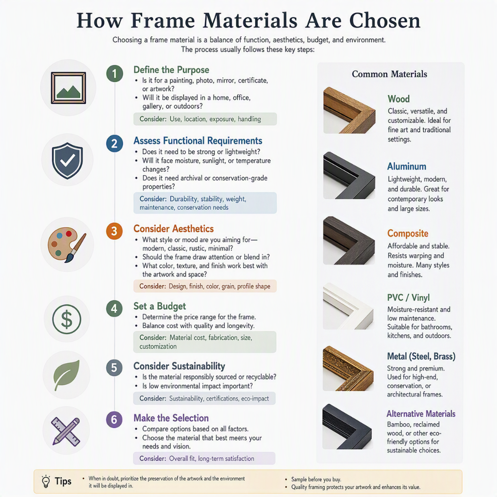
How frames materials are chosen?

Frame material selection is a balance of comfort, durability, style, cost, and biocompatibility. Here’s how and why specific materials are chosen:🧬

1. Key Selection CriteriaFactor Why It MattersWeight Heavier frames cause nose bridge pressure, headaches, and slippingFlexibility Must bend without breaking for comfort and durabilityHypoallergenic Nickel allergies are common; skin contact mattersDurability Resistance to scratching, corrosion, impactAdjustability Some materials hold adjustments better than othersCost Balances performance with affordabilityStyle Color, finish, thickness, and design flexibilityPrescription Needs Strong lenses need sturdy frames; rimless need specific materials🔩

2. Common Frame MaterialsPlastic-Based· Cellulose Acetate: Most common plastic. Made from cotton fibers + acetic acid. Adjustable with heat, hypoallergenic, wide color range. Not as durable as some synthetics.· Cellulose Propionate: Lighter and more flexible than acetate. Resists aging and discoloration. Common in sports and children’s frames.· TR-90 (Nylon-Based): Extremely lightweight, flexible, memory-retentive. Ideal for sports and active wear. Cannot be adjusted with heat easily.· Optyl: Epoxy resin. Very lightweight, holds color well, hypoallergenic. Limited adjustability.· Polycarbonate: Impact-resistant. Often used in safety and sports frames.Metal-Based· Monel (Nickel-Silver): Classic metal alloy. Strong, adjustable, affordable. Can cause nickel allergies.· Stainless Steel: Corrosion-resistant, durable, relatively inexpensive. Heavier than titanium.· Titanium: Lightweight, strong, hypoallergenic, corrosion-resistant. Expensive. Three types: pure titanium, beta-titanium (more flexible), and titanium alloy.· Aluminum: Very light, but less durable. Often used in accents or rimless mounts.· Beryllium: Lightweight, strong, non-magnetic. Rare and expensive.· Gold-Filled / Gold-Plated: Aesthetic appeal. Gold-filled is more durable than plated.Combination & Specialty· Wood: Eco-friendly, unique look. Not adjustable, susceptible to moisture.· Horn / Bone: Traditional, luxury. Heavy, expensive, requires care.· Carbon Fiber: Ultra-light, strong, modern. Expensive.· 3D-Printed Resin: Fully customizable, rapid prototyping. Limited color and finish options.🎯

3. How the Choice Is MadeBy the Manufacturer:· Target Market: Kids → flexible, durable (TR-90, propionate). Luxury → titanium, gold, horn. Sports → TR-90, polycarbonate.· Cost Target: Budget → monel, acetate. Premium → titanium, carbon fiber.· Design Intent: Rimless → titanium or beta-titanium (needs strength). Thick frames → acetate (color, style).By the Optician/Patient:· Face Shape & Size: Larger faces need wider frames; material affects weight.· Skin Sensitivity: Nickel allergy → titanium or acetate.· Lifestyle: Active → TR-90, titanium. Office → acetate, stainless steel.· Prescription Strength: Strong prescriptions → smaller frames + high-index lenses + sturdy material (titanium).· Budget: Determines the material tier.⚖️

4. Trade-OffsMaterial Weight Durability Adjustability Cost Allergy RiskAcetate Medium Medium High Low LowTR-90 Very Low High Low Medium LowMonel Medium Medium High Low HighStainless Steel Medium High Medium Low LowTitanium Very Low Very High Low High Very LowCarbon Fiber Very Low Very High Very Low Very High Very Low🔬

5. Testing & Standards· Flex testing: Bending temples repeatedly to check fatigue.· Impact testing: Drop tests and ball impacts (especially for children/sports).· Corrosion testing: Salt spray for metal frames.· Skin compatibility: Nickel release testing (EU Nickel Directive).· Color fastness: Sweat and UV exposure tests.💡

Key InsightFrame material is chosen by answering three questions:

1. Who is wearing it? (Child, athlete, professional, elderly)2. What does it need to do? (Hold heavy lenses, survive impact, look luxurious)3. What can it cost? (Budget, mid-range, premium)The material determines comfort, lifespan, and style—but the fit is what makes it truly wearable.Would you like to know how frame shape is chosen for different face types, or how rimless frames are engineered?

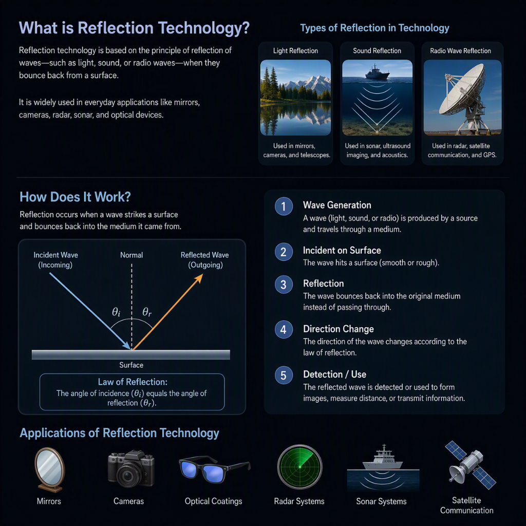
what is the reflection technology? How does it work?

Reflection technology refers to systems that use the bouncing of light (or other waves) off surfaces to detect, measure, identify, or manipulate objects. It works on a simple principle: send a signal out, measure what comes back, and calculate what that tells you about the target.🔦 The Core PrincipleWhen light hits a surface, some of it reflects. How it reflects depends on:· Surface angle — flat mirrors reflect cleanly; rough surfaces scatter· Material — metal reflects differently than glass or skin· Wavelength — infrared, visible, and UV behave differently· Distance — time delay reveals how far away the object is📡 How It Works: Step by Step“`1. Emit a signal (light, laser, IR, radar, sound) ↓2. Signal travels to target ↓3. Signal bounces off target ↓4. Sensor captures the returning signal ↓5. System measures: time, angle, intensity, wavelength shift ↓6. Algorithm converts data into information“`🔬 Types of Reflection Technology1. Time-of-Flight (ToF)· Sends a pulse of light (usually IR)· Measures how long it takes to return· Formula: Distance = (Speed of Light × Time) ÷ 2· Used in: Depth cameras, LiDAR, iPhone Face ID2. LiDAR (Light Detection and Ranging)· Fires thousands of laser pulses per second in a grid pattern· Builds a 3D point cloud of the environment· Used in: Autonomous cars, drones, mapping, archaeology3. Radar (Radio Detection and Ranging)· Uses radio waves instead of light· Works through fog, rain, and darkness· Used in: Air traffic control, weather tracking, adaptive cruise control4. Sonar (Sound Navigation and Ranging)· Uses sound waves (underwater)· Measures echo return time· Used in: Submarine navigation, fishing, medical ultrasound5. Optical Reflectometry· Sends light into a fiber or surface· Analyzes the reflected pattern to detect faults, temperature, or strain· Used in: Fiber optic networks, structural health monitoring6. Specular vs. Diffuse Reflection Sensing· Specular: Mirror-like reflection — used in laser barcode scanners· Diffuse: Scattered reflection — used in optical mice, proximity sensors🧠 How the System Interprets ReflectionThe reflected signal carries information:What Changes What It RevealsTime delay Distance to objectAngle of return Direction and shapeIntensity Surface reflectivity, materialWavelength shift Speed of object (Doppler)Polarization change Surface roughness, stressPhase shift Sub-millimeter precision🏭 Real-World ApplicationsMedical Imaging· Optical Coherence Tomography (OCT): Uses reflected near-infrared light to create cross-sectional images of the retina — detecting macular degeneration, glaucoma, and even coronary plaque.Automotive· LiDAR and radar let self-driving cars “see” obstacles, lane markings, and pedestrians in 3D.Consumer Tech· Face ID: Projects 30,000 IR dots onto your face and measures the reflected pattern.· Optical mice: LED light reflects off the desk surface; a sensor tracks movement.· Proximity sensors: Your phone screen turns off when it detects your face’s reflection.Industrial· Laser profilometers: Scan surfaces to detect defects in manufacturing.· Fiber Bragg Grating sensors: Measure strain in bridges and pipelines via reflected wavelength shifts.Military & Aerospace· Laser range finders: Measure distance to targets.· Synthetic Aperture Radar (SAR): Creates high-resolution images through clouds and darkness.💡 Key InsightReflection technology works because light (or waves) carry information when they bounce. The system doesn’t just see the object—it measures how the object changed the signal. That change reveals distance, shape, material, motion, and even internal structure.Would you like to go deeper into a specific type, such as LiDAR for autonomous vehicles or OCT for medical imaging?

What is the use of lens in making and analazying small nano & microbes objects?

Lenses are essential tools for both making and analyzing nano-objects, but they work in fundamentally different ways depending on the task: optical lenses use light to manipulate or observe, while electron lenses use electromagnetic fields to achieve atomic-scale resolution.

🔬 Making Nano-Objects: Optical Lithography

For manufacturing, lenses focus light to “write” patterns on a tiny scale.

· Immersion Lithography: A high-index liquid (like water) is placed between the lens and the silicon wafer, increasing the Numerical Aperture (NA) and allowing smaller features to be printed.
· Solid Immersion Lens (SIL): A high-index solid lens is placed in near-contact with the sample. It focuses light into a spot smaller by a factor of the material’s index (n or n²), enabling sub-wavelength patterning.

👁️ Analyzing Nano-Objects: Breaking the Diffraction Limit

For observation, lenses either enhance optical resolution or switch to electrons entirely.

· Super-Resolution Optical Techniques: Microsphere lenses placed near the sample convert near-field (evanescent) waves into propagating ones, allowing standard microscopes to resolve features as small as 65–87 nm. Metasurfaces (flat lenses) can also track nanoparticles with 10 nm accuracy.
· Electron Lenses (TEM/SEM): Because electrons have much shorter wavelengths, electromagnetic “lenses” can resolve down to sub-0.1 nm (atomic scale). This is far beyond the ~200 nm limit of visible light.

🎯 Manipulating Nano-Objects: Optical Tweezers

Lenses are also used to trap and move individual nanoparticles.

· Optical Tweezers: A tightly focused laser beam creates a gradient force that holds a particle at the focus. By steering the beam, particles can be moved, stretched (like DNA), or sorted.

If you’d like to dive deeper into a specific technique, such as how immersion lithography prints chips or how electron lenses correct aberrations, feel free to ask.